
We continue exploring JavaScript as a language for embedded development using JerryScript and the Particle Photon. In this post we will use the code we wrote for our first post to build a sensor hub with remote monitoring and alarms through e-mails. This is the second post in the series. Take a look at the first post where we got JerryScript up and running on the Particle Photon.
“Build a sensor hub with remote reports using JavaScript and the Particle Photon!”
Tweet This
Introduction
In our previous post we had a look at the different alternatives for embedding JavaScript in memory-limited devices such as microcontrollers. We explored the pros and cons of doing so, and we picked two JavaScript engines and two microcontrollers to run some tests. JerryScript and Espruino for the JavaScript engines, and the Particle Photon and the ESP8266 for the hardware. The previous post focused on getting JerryScript running on the Particle Photon. To do so we developed a small glue library, JerryPhoton, to expose parts of the Wiring API (used by the Particle Photon) through JerryScript. We run some tests with success and called it a day. Now it's time to do something useful with all of that.
In this post we will turn the Photon into a sensor hub. A sensor hub is simply a microcontroller that connects to different sensors, reads the data from them, and then does something useful with it. In our case, we will periodically check for certain critical conditions and send an alarm through e-mail when these conditions are triggered. We will also send periodic reports of all sensor data to a web service where it can be further processed.
Basic Sensor Electronics
In this post we will work with sensors. Sensors are special electronic devices that can turn some physical parameter into an electrical signal. Of course, each sensor handles this "conversion" in its own way. Some sensors are simple, using known physical effects that result in interactions with electromagnetism, while others are "smart": they come with integrated circuits that can turn raw physical interactions into an easier to read electric signal.
For example, one of the simplest sensors is the thermocouple. A thermocouple is simply different types of conductors joined at junctions. These conductors, due to the Seebeck effect, generate a voltage that varies according to temperature. So a thermocouple turns temperature into voltage. If you have a way of reading voltage, with a thermocouple, you also have a way of reading temperature. Microcontrollers usually have the necessary hardware to measure changes in voltage: analog digital converters (ADCs), so it is possible to sense temperature with a thermocouple and a microcontroller. Neat!
Other sensors, however, can be more complex. For instance, in this post we will use a humidity sensor. Some humidity sensors, like the one used for this post, work by measuring changes in the capacitance of a special internal component. Measuring capacitance is not as simple as measuring voltage, so it is usually not possible to read this parameter directly with a microcontroller. Some sensor manufacturers integrate a controlling circuit that can perform these measurements and turn them into something easier to read, like a series of voltage pulses. This is the case with the DHT11 sensor used in this post. We will talk more about it later.
Before we begin talking in detail about the sensors we picked, it is important to understand a few key concepts. If you are familiar with basic electronics this may not be necessary and you can skip the following section.
Voltage Limits
You may have noticed we talked about "voltage" and "capacitance" in the paragraphs above. These are basic electrical concepts. Although it is not necessary to understand them to do what we are about to do, it is important to know certain limits to prevent damage to your equipment while running experiments. Of special importance are the concepts of "voltage" and "current".
You can think of voltage in terms of "pressure". The higher the voltage, the higher the "electrical pressure" present between two points. Just like pressure in a water pipe, higher voltage means it is harder to "stop" the flow of electrical current. Electronic, and in particular, digital circuit components have very strict limits on the amount of voltage they can take. Electronic components exposed to voltage levels outside their limits may stop working permanently, or worse. It also important to note that components also have minimum voltage requirements. In general, exposing a component to lower voltages than required may result in malfunction but no permanent damage. However, this is not always true: some circuits can cause damage to components that drop below minimum voltage requirements, so it is important everything is always running within spec.
Microcontrollers, just like any other digital circuit, have very strict voltage limits. In particular, some general purpose I/O pins (GPIO pins) in the Particle Photon can take a maximum of 3.3 volts, while others can take 5 volts. No pin from the Photon can handle more than 5 volts. If you are working with your own sensors and equipment, make sure never to exceed these limits. You can check which pins can take 5 or 3.3 volts here.
Current is another important concept. You can think of it as the rate of flow of electrons through a wire. In other words, how many electrons are passing through a wire per second. Just like it would happen on a water pipe, increasing the "pressure" (voltage) results in a higher rate of flow (current). Digital circuits also have strict requirements with regards to the maximum current they can handle (both as input and output). It is important to stay within these limits to prevent malfunction or damage.
Fortunately for us, sensing is usually performed by reading voltage values. Sensors are connected to input pins in the microcontroller that read voltage levels, either "high" or "low" (digital pins), or a gradient of levels (analog-digital converter pins). Although current is involved in these readings, its value is of less importance. In particular, most sensors require that the current between them and the equipment performing the readings (the microcontroller) be kept as low as possible. Input pins in the microcontroller are not perfect, so a small amount of leakage current is always flowing between sensors and them. The value of this current is very small and well within specification.
Pull-up and Pull-down Input Circuit Configurations
There is one more important piece of information you must be aware of when working with sensors: input circuit configurations. Sensors are connected to input pins of the microcontroller. There are two types of sensors: analog and digital.
Analog sensors produce a range of voltage of values between sensor defined values. For instance, a temperature sensor might produce values between 0 and 3.3 volts for a range of temperatures of 0 to 80 degrees celsius.
In contrast, digital sensors only work with two voltage levels: a low level and a high level, or 0 and 1. Some sensors use these two levels to signal a condition. For instance, a movement sensor may set a high-level in its output pin when movement is detected. Sensors that provide more complex information, like the humidity sensor described before, may use an integrated circuit (IC) to send serial data: a series of timed high and low values.
When working with both analog and digital sensors it is important to make sure the highest voltage level (the highest value for the analog sensor and the high level for the digital sensor) are always within range of the safe voltage levels for the input pins of the microcontroller.
When working with digital sensors, especially those that work as a simple flag for a condition (like our motion sensor from before), it is important to understand how the high and low levels of voltage are produced. In particular, it is important to know whether the sensor includes an internal pull-up or pull-down resistor. To understand why this matters, we'll draw some diagrams. The following diagram shows a motion sensor acting as a switch connected to a microcontroller.
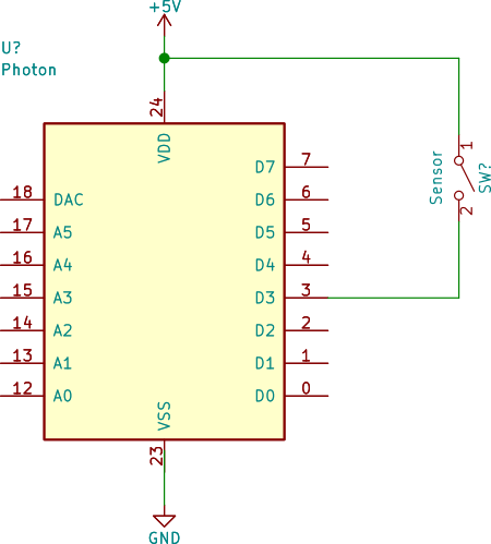
As you can see from the diagram above, the sensor is connected to a power source. This power source provides the necessary voltage to signal a high-level condition to the microcontroller. When the sensor detects movement, the switch is closed and the power source is connected directly to the input pin of the microcontroller. The microcontroller can read this voltage as a "1". Now consider the opposite case: the sensor is at rest and no movement is being detected. When this happens the switch is in an open state. Take a look at what happens with the wire that goes to the input pin of the microcontroller. It is connected to nothing! This is known as a "floating pin".
Floating pins are problematic due to the nature of how input pins work. In particular, floating pins are susceptible to charges flowing in the vicinity. They can act as capacitors or antennae, and when this happens, the microcontroller may read changes in the input value.
In the case of our motion sensor, a floating pin may result in sporadic sensing of movement, as interpreted by our microcontroller! To solve this it is necessary to modify the input circuit (the circuit connecting our sensor to the microcontroller) so that the input pin is always connected to a point with a known voltage value. In other words, when the switch is open, the input pin must be connected to the circuit ground (which has a voltage value of 0).
One way of doing this is by changing the circuit as follows:
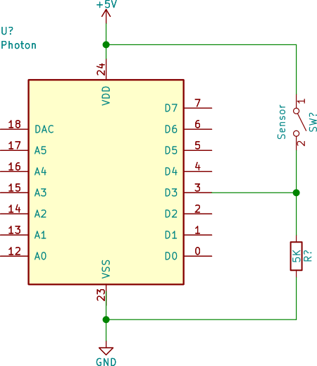
This is known as a pull-down circuit configuration. When the switch is closed (when movement is detected), the microcontroller input pin is connected directly to the power source, which is then read as a high-level. Current flows from the power source to both the microcontroller and the pull-down resistor. Pull-down resistors are usually of a value which is big enough to make sure not to exceed the maximum amount of current supported by the sensor. When the switch is opened (no movement detected), the input pin from the microcontroller is connected to the resistor, which is connected to ground. Any stray charges interacting with the wire or trace are immediately sent to ground, resulting in a consistent low voltage level for the pin.
There is another option. We could modify the circuit as follows:
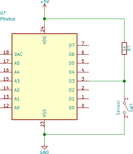
This is known as a pull-up circuit configuration. In this case, the resistor is connected to the power source. When the switch is closed, the microcontroller input pin is connected directly to the ground, causing a low-level reading. When the switch is opened, the input pin is connected to the power source through the resistor. When current flows through a resistor it causes a voltage drop. This means that the voltage read by the microcontroller is in fact lower than the voltage provided by the power source. However, the amount of current that flows through the input pin is very small, which means the voltage drop is really small. This means that even if the voltage read by the microcontroller is lower than the voltage of the power source, it still is high enough to be read as a high level or 1.
Some sensors integrate their own pull-up or pull-down resistors in their design. In this case, it is not necessary to provide them externally. Some microcontrollers, like the Particle Photon, can enable internal pull-up or pull-down resistors though software! This means that even if your sensor works as a simple switch without a pull-up/pull-down resistor, you still can skip setting it up externally.
To know whether a pull-up or pull-down resistors are required, you must check the datasheet provided by the manufacturer of the sensor. This datasheet has other important information, like the voltage required by the sensor, and the voltage of the output generated by it.
The Sensors
Now that we have a basic knowledge of what is necessary to start playing with some sensors, it is time we looked at the ones we picked for this post. Our sensor hub will be composed of four sensors:
- A pyroelectric or passive infrared (PIR) motion sensor
- An MQ-2 gas sensor
- A DHT11 humidity sensor
- An infrared flame sensor
WARNING: our sensor hub is for educational purposes ONLY. You should not rely on it for detecting potentially lethal situations like fires, gas leaks or intrusions. If you need detectors for these events, buy certified equipment and services.
The PIR Motion Sensor
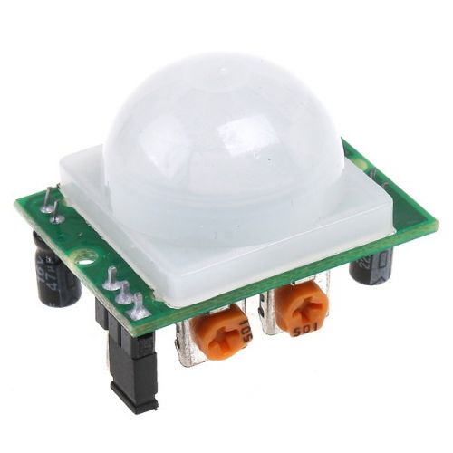
A passive infrared motion sensor is a device that detects movement by measuring the presence of heat sources. To do this a special type of material that is sensitive to temperature changes is used in it. Very minor temperature changes in this material can be induced by heat sources like humans and animals, which emit heat in the form of infrared radiation. These sensors are cheap and have a good range (around 7 meters).
Since the way the heat sensitive material interacts with heat sources is complex, most PIR sensors come with a controlling integrated circuit. For our sensor hub we will be using the HC-SR501 PIR motion sensor. This sensor is currently listed in Amazon at $10 for a bundle of 5 sensors. It works with a good range of voltages (5V to 20V), outputs a maximum of 3.3V, can hold the trigger signal internally (for detecting very small of quick movements) and consumes very little power. The sensor has three pins: ground, output and power. The HC-SR501 does not require a pull-up or pull-down resistor since it never acts as a simple switch: the output is always connected to either 3.3V or 0V. All we need to do to use it simply power it and connect its output directly to a digital input pin on the microcontroller.
The MQ-2 Gas Sensor
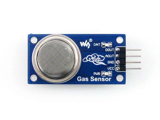
The MQ series of sensors are capable of detecting different types of gas. The MQ-2 sensor, in particular, can detect methane, butane, LPG, smoke, alcohol, hydrogen and propane. These sensors have the peculiarity of needing heat to operate properly, therefore they usually come with an integrated heating resistor. We will be using the SUKRAGRAHA MQ-2 sensor which is currently listed in Amazon at $6.99. This sensor includes a controlling integrated circuit that provides both analog and digital outputs. We will be using the analog output so we can manually calibrate the threshold at which the alarm will go off. The sensor comes with four pins: power, ground, digital out, and analog out. The analog output is rated below 3.3V so we can connect it directly to an analog-digital-converter pin in the microcontroller. The sensor requires a one-time 24 to 48-hour burn-in period to give accurate readings, so before using it make sure to connect it a 5V power source (power and ground pins only) for that period of time. If you don't this, the sensor will still work, however the readings may vary a lot after power-on. Each time you power on the sensor for the first time, it will start heating up to its recommended operating temperature. Before reaching this temperature, which should take a couple of minutes, readings will also be inaccurate. The sensor can be powered by a 5V power source.
To test this sensor you can use a common butane lighter without igniting the flame.
The DHT11 Humidity Sensor
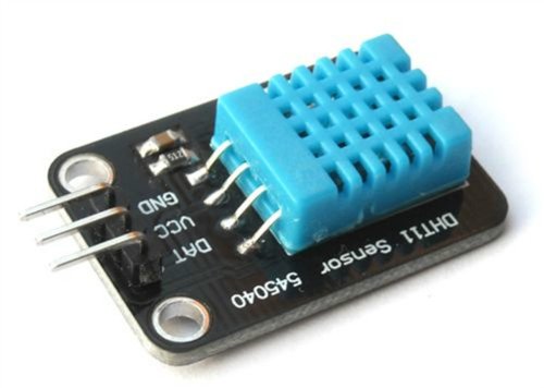
The DHT family of humidity sensors are convenient, low-cost sensors with a digital output. They measure both humidity (through capacitance) and temperature (through a thermistor) and have only three pins. Information is sent through a very simple serial protocol. The DHT11 sensor is currently listed at $6.99 in Amazon. The DHT22 is a similar but more accurate version of the same sensor. Both sensors can operate in a range of 3 to 5V. Although an integrated circuit is used to generate the serial information signal with its data, a pull-up resistor is required for the output pin. The integrated pull-up resistor in the Photon works fine for this.
The Infrared Flame Sensor
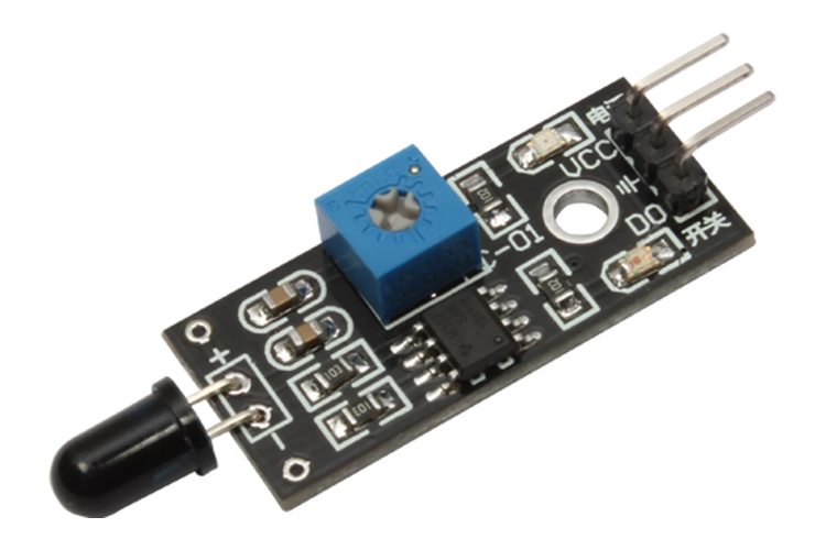
In addition to the gas detector, we will use an infrared flame detector. Flame detectors work by filtering specific light wavelengths that are produced when a flame is ignited. They are composed of a light-sensing diode and a light filter. The sensor we will use is listed in Amazon at $6.99 and comes with an integrated circuit controller that outputs a digital signal (1 or 0). It can be connected directly to a digital input pin on the microcontroller and works with both 3.3 and 5V power sources.
To test this sensor you can use common matches. If you light a match close enough to the sensor, it will pick up the radiation emitted while igniting it.
The Sensor Hub
Now that we have all the sensors that will be part of our sensor hub it is necessary to connect them to the microcontroller. Since we are only doing this for educational purposes, we will use a solderless breadboard as base. A breadboard is a board that allows us to connect electronic devices together without soldering them. It provides linked "slots" with the proper spacing and diameter to fit pins from many devices. The spacing from the pins in the Particle Photon, for example, fits perfectly in a common breadboard. You can find one listed at Amazon for $5.
Take a look at this site if you want to learn more about how to use breadboards.
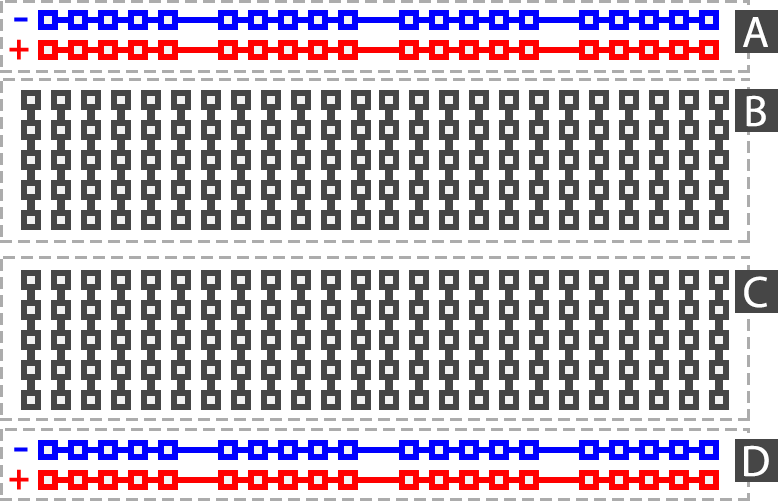
As you can see breadboards have "stripes" or "buses" of connected slots. The outermost buses are horizontal and run along the length of the breadboard. They are usually marked with "+" and "-" symbols in red and blue. These buses are commonly used for the power source. In our circuit, we will connect a 5V power source to the "+" bus and the ground to the "-" bus. Do note that the buses on each side are not interconnected. In other words, if you send 5V to the "+" bus on one side, you still need to connect the same power source to the other side. All buses are independent.
The inner buses are vertical and, just like the outermost buses, they are separated at each side of the breadboard. For small breadboards like the one used in this example, each of the inner buses only shares 5 vertical pins.
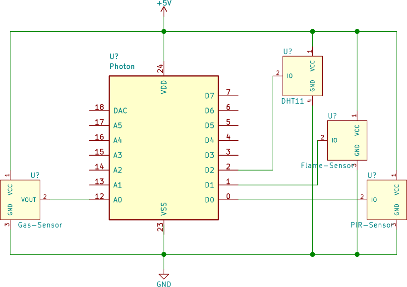
Here's how to connect the sensors to the Photon:
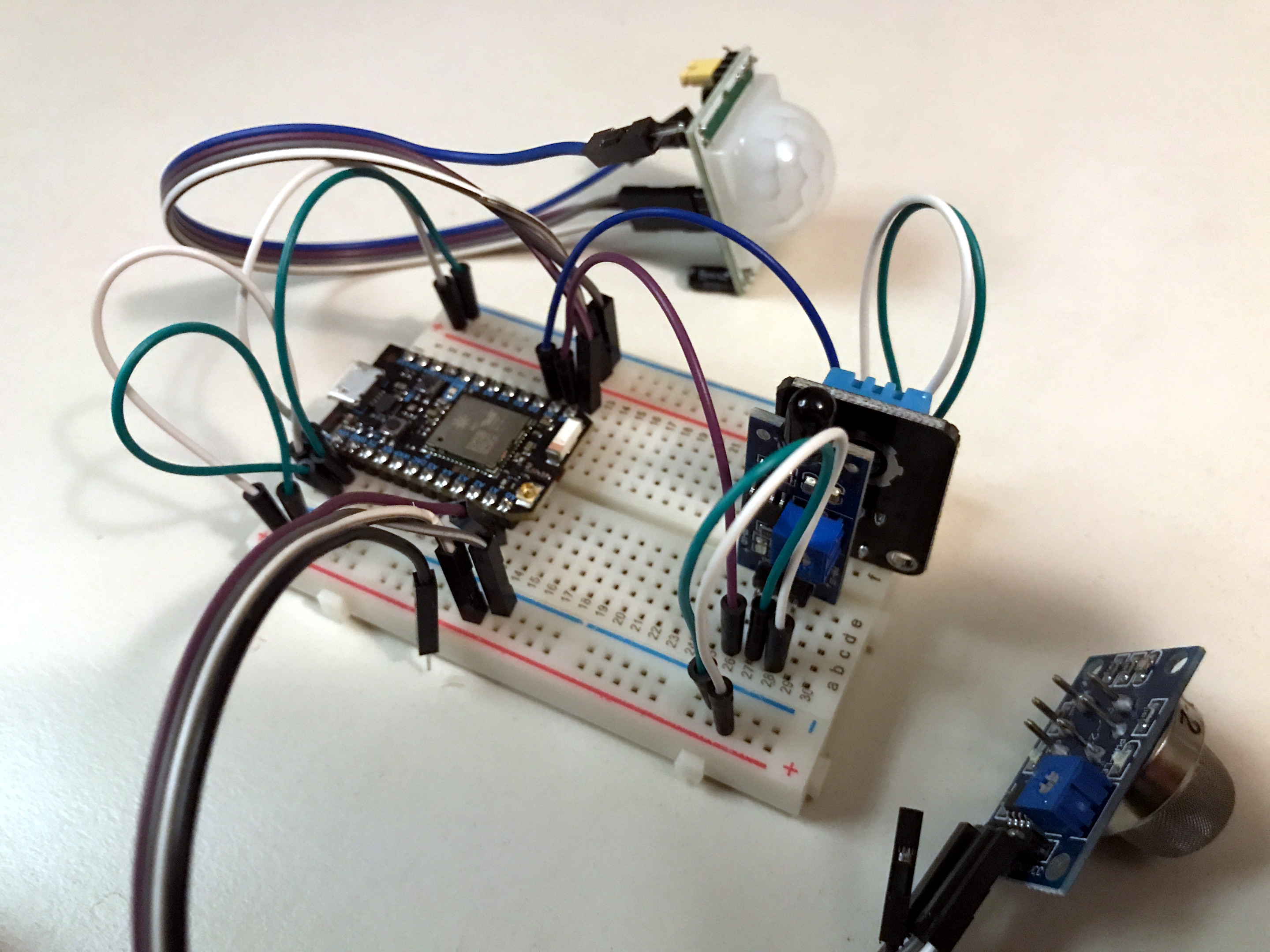
And here's how it looks on the breadboard:
If you buy a breadboard, get a wire pack so you don't need to build your own.
For convenience, the Particle Photon allows you to use one of its pins as a power source for external devices. The current is limited to 1A per the Photon's datasheet. This is more than enough for our sensor hub. This means that if you connect the Photon to an USB power source that can provide more than 1A of current, you don't need an external power source for the sensors. Most modern desktop motherboards can do this. Smartphone chargers are also usually rated for more than 1A, so getting a power source for our sensor hub is really simple.
Once you have connected everything as shown above, it's time to flash the Photon with our firmware!
Code Changes
We have made some updates to the code shown in the first article. We have added a small C library for reading the DHT11 sensor output. We have also exposed this library through JerryScript so that we can use it from JavaScript (through the dht11 object). The dht11 exposes only one function: read. The read function takes the pin number where the DHT11 sensor is connected and returns an object with two fields: humidity (percentage) and temperature (celsius). That's it!
Our sensor project also needs to report to a remote server. However, as we explained in part 1, to do so safely we would need some sort of encryption. Now, there are three ways of accomplishing this:
- Use a small C library that provides a strong encryption suite and can work with very little RAM and ROM. There are some libraries that could do this, but rolling your own encryption is almost always a bad idea. Let's check the other options.
- Embed a TLS library and add TLS support to the TCP sockets provided by the firmware. This works and there are very good alternatives for small TLS libraries, as long as you don't choose to embed all certificate authorities' (CA) certificates (which can weigh more than 1MiB). Even if you choose to embed just the certificates required for your servers, this is still problematic since it would require us to use up more ROM space, which is very limited in the Photon for user applications. In fact, the Particle firmware already embeds a TLS library, however it is not available for use for user applications.
- Use Particle's publish/subscribe API to send events through their servers. Particle's API allows us to create small, rate-limited events that can then be sent to their servers. Particle servers have integration options to forward these events to external servers. Since our payload will be really small, and the communication between our sensor hub and our own server needs to be encrypted, this looks like the best alternative. This obviously makes us dependent on Particle's servers, but for our purposes it is good enough.
We have exposed Particle's publish event through the photon.publish function in JavaScript. The photon.publish function takes one or two parameters:
photon.publish(event, data):eventis an event name (string).datais an optional string with a payload to send along with the event. If sending fails an exception is raised.
Now that we have all that we need integrated with the firmware, it is time to flash it!
Flashing the Photon
Since our code changes have forced us past the 128KB of flash memory for user applications in the Photon, we had to disable one big Photon feature to be able to use some additional ROM space. The standard Particle firmware reserves 128KB of space to download firmware updates from the cloud. If you disable this feature, you get access to an additional 128KB of ROM space. We have modified the firmware to do this in the sensor_hub version of our Docker image. So, to flash the latest version of our firmware you need to follow the same steps from the first post. First get the code:
git clone https://github.com/auth0-blog/javascript-for-microncontrollers-example-sensor-hub
Flashing Using the Docker Image (Linux Hosts)
If you are running our Docker image on a Linux host, flashing the compiled firmware is really easy:
- First, you need to connect your Photon to the computer using a USB cable.
- Now put the Photon in Device Firmware Upgrade (DFU) mode. DFU mode is a special mode that can be used to update firmware even if the previous firmware is bad. This is possible thanks to the bootloader that is installed inside each Photon. To enter DFU mode, press and hold the
SETUPbutton. While holding theSETUPbutton, quickly press and release theRESETbutton. Keep holding theSETUPbutton until the main LED starts flashing yellow. You can now release all buttons. - Run the Docker container using the following script:
./compile-and-flash.sh
If you take a peek at the script, you will notice we are now giving the container full access to our USB devices. This is necessary for the container to send the firmware image to the Photon. After a few seconds, your Photon will reboot and you will see a flashing blue LED.
If you are running macOS or Windows, see the first post to see how to flash the Particle Photon.
We have not loaded our new sensor hub code yet. Let's do that!
Sensor Code
The sensor code is located at js/sensors in the example. Since JerryScript supports ECMAScript 5.1, we can use Babel to transpile ECMAScript 2015 to it. Here's what our sensor hub code looks like:
const interval = 5000;
const host = 'i5-4590-LIN';
const eventReport = 'sensor-report';
const eventAlarm = 'sensor-alarm';
const port = 3000;
const gasThreshold = 1000;
const tempThreshold = 40;
const alarmWaitMs = 5000;

const pins = {
    movement: photon.pin.D0,
    flame: photon.pin.D1,
    humidity: photon.pin.D2,
    gas: photon.pin.A0
}

Object.keys(pins).forEach(k => {
    photon.pin.mode(pins[k], 'INPUT');
});

photon.pin.mode(pins.humidity, 'INPUT_PULLDOWN');

function readSensors() {
    const dht = dht11.read(pins.humidity);
    return {
        movement: photon.pin(pins.movement),
        flame: !photon.pin(pins.flame),
        humidity: dht.humidity,
        temperature: dht.temperature,
        gas: photon.pin(pins.gas)
    };
}

function checkData(data) {
    return data.movement ||
           data.flame ||
           (data.gas > gasThreshold) ||
           (data.temperature > tempThreshold);
}

function sendData(data) {
    const client = photon.TCPClient();

    client.connect(host, port);
    if(!client.connected()) {
        photon.log.error(`Could not connect to ${host}, discarding data.`);
        return;
    }

    client.write(JSON.stringify(data) + '\n');
    client.stop();
}

function sendEvent(event, data) {
    try {
        const datastr = JSON.stringify(data);
        photon.log.trace(`Sending event ${event}, data: ${datastr}`);
        photon.publish(event, datastr);
    } catch(e) {
        photon.log.error(`Could not publish event: ${e.toString()}`);
    }
}

let data = {};
let timeSinceAlarmMs = 0;

// Check sensors as fast as possible for values outside the normal thresholds
setInterval(() => {
    timeSinceAlarmMs += 500;

    try {
        data = readSensors();
        if(checkData(data)) {
            photon.pin(photon.pin.D7, true);
            if(timeSinceAlarmMs >= alarmWaitMs) {
                sendEvent(eventAlarm, data);
                sendData(data);
                timeSinceAlarmMs = 0;
            }
        } else {
            photon.pin(photon.pin.D7, false);
        }
    } catch(e) {
        photon.log.error(e.toString());
    }
}, 500);

// Send a snapshot every interval milliseconds
setInterval(() => {
    try {
        sendEvent(eventReport, data);
        sendData(data);
    } catch(e) {
        photon.log.error(e.toString());
    }
}, interval);
In less than 100 lines this code sets up the necessary pins as inputs, periodically sends reports and checks for critical values, and sets up two ways of sending data: one through a TCP socket (for reports to the local network) and another through Particle events.
To load this code be sure to first compile it:
cd js
npm install
node_modules/grunt/bin/grunt
../upload-script.sh dist/sensors.js <YOUR-PHOTONS-IP>
That's it! Whenever a critical condition is triggered, the blue LED will light up. You can use this to quickly calibrate the sensors to the right values. Some sensors provide potentiometers to do hardware adjustments to their thresholds (use a screwdriver for this). For the gas sensor, you can modify the threshold directly in the script. Don't forget to recompile it before uploading it! Do not forget the gas sensor also needs to reach the proper internal temperature to do accurate reads, do not calibrate it before this.
Now let's set up what is necessary to receive remote reports in our smartphone!
A Webtask for E-mail Alerts
To receive remote alarms we will set up a server that can receive events from the Particle cloud. This server will then forward to us the event through an email! This means that whenever a critical condition is triggered by one of the sensors, we will receive a notification in your smartphone! How cool is that?
Actually, thanks to Webtasks we don't need a server. Webtasks provide a way to just upload code and have it running without having to manage a server. They are "Node.js functions on the cloud". Webtasks can use NPM libraries like Express, this means that for our server we can do the following:
'use latest';

const express = require('express');
const webtask = require('webtask-tools');
const bodyParser = require('body-parser');
const sendmail_ = require('sendmail')();
const Promise = require('bluebird');

const sendmail = Promise.promisify(sendmail_);

const app = express();

function checkCredentials(req, res, next) {
    const secret = req.webtaskContext.secrets.secret;
    const coreid = req.webtaskContext.secrets.coreid;

    const reqSecret = req.get('Secret');
    const reqCoreid = req.body.coreid;

    if(secret === reqSecret && coreid === reqCoreid) {
        next();
    } else {
        console.log(`Unauthorized request by ${req.ip}`);
        res.sendStatus(401);
    }
}

app.use(bodyParser.urlencoded({ extended: true }));
app.use(checkCredentials);

function sendEmail(context, data) {
    const promisifyOpts = { context: context.storage };
    const storageGet = Promise.promisify(context.storage.get, promisifyOpts);
    const storageSet = Promise.promisify(context.storage.set, promisifyOpts);

    return storageGet().then(stored => {
        if(!stored) {
            stored = {};
        }

        const last = stored.lastEmailTimestamp ? stored.lastEmailTimestamp : 0;
        const minPeriod = context.secrets.emailMinPeriod;
        const now = Date.now();
        const timediff = now - last;

        if(timediff > minPeriod) {
            const pretty = JSON.stringify(JSON.parse(data), null, 4);

            return sendmail({
                from: 'sensors-webtask@webtask',
                to: context.secrets.email,
                subject: 'SENSOR ALARM',
                text: pretty
            }).then(() => {
                stored.lastEmailTimestamp = now;
                return storageSet(stored);
            });
        }
    }, e => {
        console.log(`Error while sending e-mail: ${e.stack}`);
    });
}

app.post('/', (req, res) => {
    if(req.body.event === 'sensor-alarm') {
        sendEmail(req.webtaskContext, req.body.data).finally(() => {
            res.end();
        });
    } else {
        res.end();
    }
});

// Expose this express server as a webtask-compatible function

module.exports = webtask.fromExpress(app);
You can find the code for this in the webtask folder of the example. As you can see the code handles HTTP requests. It does two things:
- It checks for the right credentials. Since the Webtask is public, anyone could use it. We prevent that by checking for the right
secretandcoreidparameters embedded in the request. Thecoreidparameter is embedded by the Particle cloud and is the unique ID of your Particle device. Thesecretis a string we can manually set up in the Particle cloud. All requests to a Webtask must use TLS so these strings are not visible to outside observers. - If enough time between reports has passed, we forward the critical report to the user through an e-mail. We use the excellent
sendmaillibrary for this, a small JavaScript library that can connect directly to SMTP servers without the need for an external e-mail provider. Having a minimum time between reports serves to prevent spamming the e-mail account with unnecessary reports. This is also handled in thesensors.jsscript, but it is good practice to have the backend perform it's own checks.
Upload the Webtask!
Now it's time to get our webtask running. To do that simply run:
cd webtask
npm install -g wt-cli # Webtask command line tools (one time only)
wt init # To login to the Webtasks service (one time only)
wt create --secrets-file secrets app.js
The secrets file contains a series of key-value entries with configuration parameters for our webtask. You should create one of your own before running the last command:
secret=my_secret
coreid=Get this from https://console.particle.io/devices
emailMinPeriod=5000
email=sebastian.peyrott@auth0.com
You must set secret, coreid and email to the right values or you will not receive any e-mails.
After running wt create you will be informed of the URL of your webtask. Once you get this, the webtask is already live! Take note of the URL as we will need it to create a Particle cloud webhook below. If you forgot to copy it, run wt ls to get a list of all of your active webtasks. If you decide to make changes to an already uploaded webtask, take a look at the wt update command.
Setting Up a Particle Webhook
The last piece of the puzzle! To set up a Particle cloud webhook ("integration"), you can either use the web console or the particle command line client. I had trouble using the web console as there appears to be some issues with the parsing of URLs as generated by webtasks (which are valid per RFC 3986). I have reported this to the Particle team and they assured me they would look into it. Unfortunately this prevents us from using the Particle web console for now. Fortunately, the command line client works wonderfully. To create a Particle webhook first edit the following file:
{
      "event": "sensor-alarm",
      "url": "Get this from wt ls",
      "deviceid": "Get this from https://console.particle.io/devices",
      "requestType": "POST",
      "headers": {
          "Secret": "my secret"
      },
      "rejectUnauthorized": "true"
}
Take special note of the following keys: url, deviceid, and headers.Secret. Complete this so that they match the URL created with the wt tool and use the same device id (core id) and secret. After you have done this, save the file as particle-webhook.json.
Now to finally create the webhook:
particle webhook create particle-webhook.json
After you receive confirmation everything should be up and running! If the command above fails, make sure that you are logged in to the Particle cloud:
particle login
Testing Everything Together
Now that we have all parts of our sensor hub system running, it's time to test it!
WARNING: our sensor hub is for educational purposes ONLY. You should not rely on it for detecting potentially lethal situations like fires, gas leaks or intrusions. If you need detectors for these events, buy certified equipment and services.
Testing the Motion Sensor
Testing the Gas Sensor
Testing the Flame Sensor
Conclusion
We had a look at a practical application of JavaScript in an embedded platform. Although we succeeded in developing a useful sensor hub, we found the experience hard to recommend to beginners. Was it worth it to spend so much time adapting JerryScript to our purposes? The resulting JavaScript code was concise and easy to read, but it was too short to justify all the effort spent on integrating it. Our JerryPhoton library is more than 1000 lines of code! It is hard to argue in favor of spending more time developing "glue" code than actual business logic. JavaScript may remain a strong pick for scripting and for interacting with a heterogeneous development team, however we cannot imagine an embedded development team where going this route would make sense. At least not this way. It would make sense, for example, if the JavaScript code were big enough and in constant development, this way the initial cost of developing the "glue" code could be downplayed. There is, however, another case where something like this would make sense: what if we didn't have to write glue code?
There are IoT platforms that consider higher-level languages important, so they strive to provide them out of the box. One of them is Espruino, which develops a firmware for microcontrollers while providing a JavaScript API. Will JavaScript strengths be of more use in this scenario? Will we still need to resort to equal or bigger amounts of C code? Will we have trouble integrating C libraries? Will we need them? These are some of the questions we will attempt to answer in the following posts. Have fun!
About the author

Sebastian Peyrott
Senior Engineer